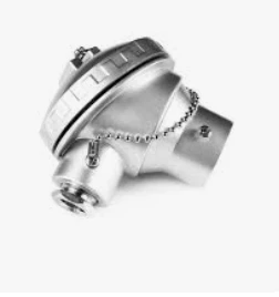
A temperature sensor can be technically correct and still be unsuitable for a particular installation. In many industrial temperature-measurement systems, the difficulty is not choosing the thermocouple itself. The real problem appears at the connection point: the thread does not match, the cable entry is different, the mounting dimension is unsuitable, or the replacement part takes up more space than the original component. For this reason, a connection head should be selected according to the complete mechanical arrangement rather than its appearance alone. This guide explains the main points to check when specifying a connection head for an industrial temperature sensor, with particular attention to the KNE configuration shown in the accompanying dimensional drawing.
Jaye Heater Technology Co., Ltd. is one of the most reliable manufacturers and suppliers of temperature sensor connection head in China, also supports custom service. Welcome to wholesale high quality temperature sensor connection head at competitive price from our factory.
A temperature-sensing assembly normally has several interfaces between the sensing point and the control instrument.
The sensing element is installed where temperature needs to be measured. The electrical connection then has to be transferred safely toward the external wiring.
The connection head sits between these two parts.
Although it is a relatively small component, its dimensions can affect the complete installation.
A mismatch may result in:
For a new machine, these issues can be prevented during the design stage.
For a replacement project, the existing component should be measured before a new part is ordered.
When requesting a connection head, simply stating a model name is often insufficient.
For example, a request for a "KNE head" identifies the general configuration, but it does not necessarily tell the manufacturer which lower connection or cable entry is required.
The drawing associated with this configuration provides several possibilities for both connection points.
The lower side can be specified with options including:
The side cable entry can be specified with:
Therefore, the correct selection begins by identifying the two interfaces separately.

A useful way to understand the component is to divide it into two connection areas.
Lower Connection
The lower connection is associated with the temperature-sensing assembly.
It determines how the connection head interfaces with the thermocouple or related sensor construction.
This is the area that needs to match the mechanical connection of the sensor side.
Side Cable Connection
The side connection is intended for the external wiring.
It determines how the cable, cable gland or corresponding fitting interfaces with the head.
These two connections do not have to use the same thread specification.
For example, a particular installation may require a metric connection on one side and a different thread standard for another interface.
The important point is that each connection should be confirmed independently.
Thread identification is one of the most important parts of the ordering process.
A common mistake is to see "1/2 inch" and assume that any 1/2-inch thread will work.
That is not the case.
G threads and NPT threads are different thread systems. Their nominal sizes may appear similar, but they are not automatically interchangeable.
For example:
G1/2" and 1/2"NPT are different specifications.
Likewise:
G3/4" and 3/4"NPT are different specifications.
Metric threads are identified differently again.
For the configuration shown in the drawing, examples include:
M20×1.5
and
M24×1.5
When ordering a replacement component, the complete thread designation should therefore be provided rather than only the nominal diameter.
An M20×1.5 designation contains two important pieces of information.
M20 identifies the nominal metric diameter.
1.5 identifies the thread pitch.
This information is important when matching the connection head with another threaded component.
The same principle applies to M24×1.5.
If the original installation uses a metric connection, the thread diameter and pitch should be checked rather than estimated from the appearance of the component.
G-thread configurations belong to a different thread standard from metric and NPT threads.
The drawing provides G1/2" and G3/4" options for the relevant connections.
When replacing an existing part, it is important to verify that the mating component was designed for the same thread standard.
This is particularly important for international OEM projects where equipment may have been designed using different regional standards.
A connection that appears close in size may still require a different component.
NPT is commonly encountered in industrial equipment using inch-based pipe-thread connections.
The illustrated configuration includes:
The NPT option should be selected only when the mating component uses the corresponding NPT thread.
It should not be chosen simply because the customer knows that the required connection is "half inch" or "three-quarter inch."
The thread standard is part of the specification.
The drawing also identifies two fitting-block options:
33 mm
and
40 mm
These dimensions are particularly relevant when the connection head has to work with a specific internal mounting arrangement.
This becomes more important during replacement work.
A customer may have an existing component that looks almost identical to the proposed replacement. However, if the internal mounting dimension is different, the new component may not accept the corresponding internal part.
For this reason, a replacement quotation should not be based solely on external photographs.
Where possible, the original part should be measured or its drawing should be supplied.
The illustrated configuration includes dimensional references of approximately:
These dimensions should be considered together with the available space in the equipment.
The issue is not simply whether the component can be connected.
The installer also needs enough space for:
This is especially important when replacing a component inside a compact machine or equipment enclosure.
A replacement part can have the correct thread and still create an installation problem if its external dimensions are unsuitable.
When an existing connection head needs to be replaced, a simple measurement process can prevent most compatibility problems.
1. Photograph the Complete Component
Take photographs from several directions.
Useful views include:
• Front
• Side
• Bottom
• Top
• Internal area with the cover removed
The photographs should be clear enough to identify the connection points.
2. Measure the Overall Dimensions
Record the main height, width and other dimensions that affect installation.
If the surrounding equipment is compact, also measure the available clearance.
3. Identify the Lower Connection
Determine the thread or mechanical connection used between the head and sensor assembly.
4. Identify the Side Cable Entry
Check the cable-entry specification separately.
Do not assume that it is the same as the lower connection.
5. Check the Internal Mounting
If the existing head contains an internal terminal or mounting component, record its mounting dimensions.
The 33 mm and 40 mm configurations shown in the drawing are examples of dimensions that may need to be confirmed.
6. Record the Required Quantity
A single replacement and an OEM production order require different quotation considerations.
The quantity should therefore be included in the initial RFQ.

A complete request does not need to be complicated.
The following information is usually enough to begin configuration verification:
| Parameter | Available Information |
|---|---|
| Configuration | KNE |
| Main dimensional reference | 80 mm |
| Additional dimensional reference | 95 mm |
| Lower fitting reference | DN32 |
| Lower external reference | DN39 |
| Fitting block | 33 mm / 40 mm |
| Probe entry options | G1/2", G3/4", 1/2"NPT, 3/4"NPT, M20×1.5, M24×1.5 |
| Wire entry options | M20×1.5, G1/2", G3/4", 1/2"NPT, 3/4"NPT |

Note: The final production configuration should be confirmed against the customer's approved drawing, sample or dimensional requirements. The values above describe the supplied configuration drawing and should not be assumed to apply to every connection-head variant.
For customized industrial temperature-sensing components, the customer's drawing remains the most reliable reference.
A drawing can define:
When no drawing is available, an existing sample can be used as a physical reference.
For initial evaluation, photographs and measurements can also be submitted.
This is particularly useful when the required component is not a standard off-the-shelf replacement.
The correct connection head is determined by compatibility, not appearance.
A component may look identical to an existing part and still have a different thread, fitting dimension or cable connection.
For the illustrated KNE configuration, the key points to check are the sensor-side connection, cable entry, thread standard, fitting dimension and available installation space.
For replacement work, start with the existing component.
For new equipment, start with the machine drawing.
For OEM production, provide the technical information before the quotation is finalized.
A clear drawing or well-documented sample can turn a vague replacement request into a precise manufacturing specification.
Hot Tags: temperature sensor connection head, China, manufacturers, suppliers, factory, wholesale, custom, price, electric, high quality, Adjustable Bimetal Thermostat Switch, BBQ NTC Temperature Sensor, Bimetal Disc Thermostats, Iron Thermostat Switch, Steam Iron Thermostat